A 2 DOF PC Controlled Camera Mount
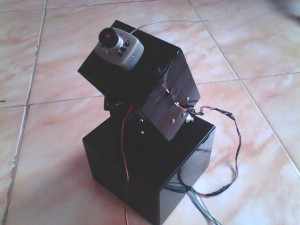
The 2 DOF PC Controlled Camera Mount is a simple project that employs 2 servo motors for the arm movements. The device can be used to hold a camera and its angle can be controlled, remotely from a PC.
BLOCK DIAGRAM EXPLANATION
The system basically consists of two major blocks
- Transmitter section
- Receiver section.
Transmitter Section
The transmitter section employs
- A n Xbee transceiver module
- RF camera receiver
Along with a Personal computer.
The Xbee transceiver module is connected to the serial port of the PC. This Xbee transceiver module is basically a high level communication protocol known as the ZigBee.
ZigBee refers to a suite of high level communication protocols using small, low power devices based on IEEE 802.15.4 standard for wireless personal area networks .This technology is simpler and cheaper than any other WPANs. ZigBee is targeted at Radio Frequency applications that require a low data rate , low power usage, and secure networking. 802.15.4 defines the physical layer, and ZigBee defines the network and application layers. In other words ZigBee is a low cost, low power , wireless mesh networking standard.
The RF camera receiver is a readymade, independent camera module.
Receiver Section
The major components of the receiver section are
- Microcontroller
- An Xbee transceiver module
- RF camera
- Actuator mechanism.
The PIC 16F73 microcontroller is the heart of the system. The microcontroller synchronizes all the work and computes necessary parameters and produces respective vector output.The receiver section is also equipped with a n Xbee transceiver module for the successful data transfer for the fine operation of the rifle mount system.
The RF camera used here is an independent readymade module.
The Actuator Mechanism employed in this project are two servo motors. One for the base clock/anticlock movement and the other for the arm up/down movement.
WORKING
Transmitter Section
As denoted earlier, the PC consists of a front end user interface written in C#.net. This application is designed in such a way that, when any of the button with in the application is pressed, a character corresponding to that button is transmitted to the remote module through the serial port. For example, if the button to turn the base clockwise is pressed, a character c is transmitted to the remote module. The front end also has a video field which displays the video that is available from the remote module.
The Xbee transceiver module connected to the serial port of the PC, simply receives the character from the PC and transmits it to its counterpart in the receiver section.
Receiver Section
The character transmitted , is received by the Xbee transceiver module in the receiver side. This character is transferred to the microcontroller through the USART peripheral. This character received by the microcontroller is compared with the predetermined character values with in the controller and further action is taken with respect to the program embedded in the microcontroller. For example, if character c is received, the program in the microcontroller compares this character with other characters determined by the programmer. If a true condition for the character c is obtained, microcontroller will execute the code to turn the servo motor clockwise.
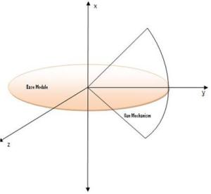
The actuator mechanism consists of two servomotors, providing a freedom of degree ‘two’, the work area of the gun is represented in the graph shown below
Servo motor has high torque and is capable of holding more weight when compared to ordinary dc motor or the stepper motor.
A servomotor consists of a DC motor with a series of gears attached to it. An internal potentiometer is used with feedback to control the movement of the motor. Normally, the output shaft is limited to 180° of rotation, but it is possible to modify a servomotor so that continuous rotation is obtained. A servomotor is controlled with pulse-width-modulated (PWM) signal. In a modified servomotor, a pulse with a width of 2 ms rotates the motor clockwise at full speed. Similarly, a pulse with a width of 1 ms rotates the motor anti-clockwise at full speed. Sending a pulse with width of 1.5 ms stops the motor.
A servomotor requires only three wires to operate: +V, ground, and the signal wire where the pulse is applied.


